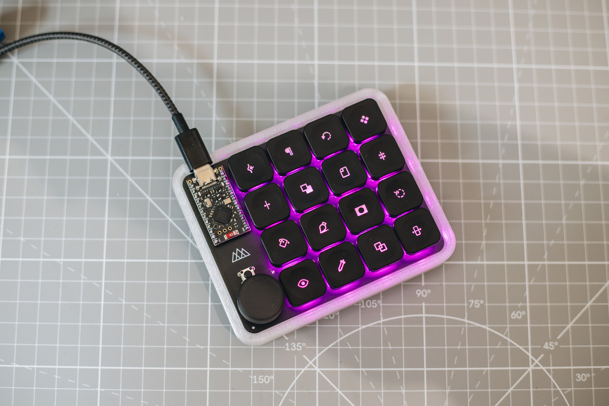
Building a MinimalPad is not that complicated if you have even a little bit of experience with soldering. It is hard to make mistakes if you follow the steps carefully. Your kit should include all the parts you need to assemble the PCB. If you ordered keycaps and switches from me as well, you should have everything you need to build a complete MinimalPad. If you have any questions or want me to clarify something, feel free to reach out at support@minimalmacropad.com
Parts list
Included with the standard kit
- 1× MinimalPad PCB
- 16× Kailh Choc low-profile hot-swap sockets
- 17× 1N4148 diodes
- 1× EC11 push rotary encoder
- 1× PCB push button
Depending on your order, you will also need
- 1× compatible microcontroller
- 1× set of male pin headers
- 16× compatible Kailh Choc switches
- 16× keycaps
No battery is included. For wireless use, source a compatible 3.7 V LiPo battery locally and check the connector polarity before connecting it.
Before you get started
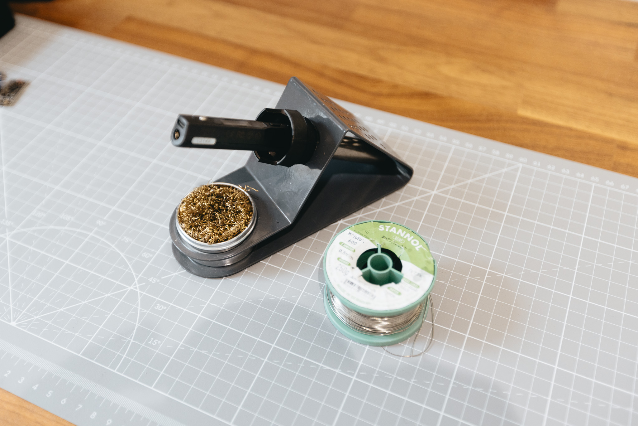
The minimum tools you need, I would say, are a soldering iron with a relatively small tip, some solder, and a pair of snips or cutters. Cleaning alcohol and helping hands are nice to have, but definitely not required. I do recommend using a good surface to solder on, since there are quite a few solder points and you do not want to get flux and solder everywhere.
Soldering
Diodes
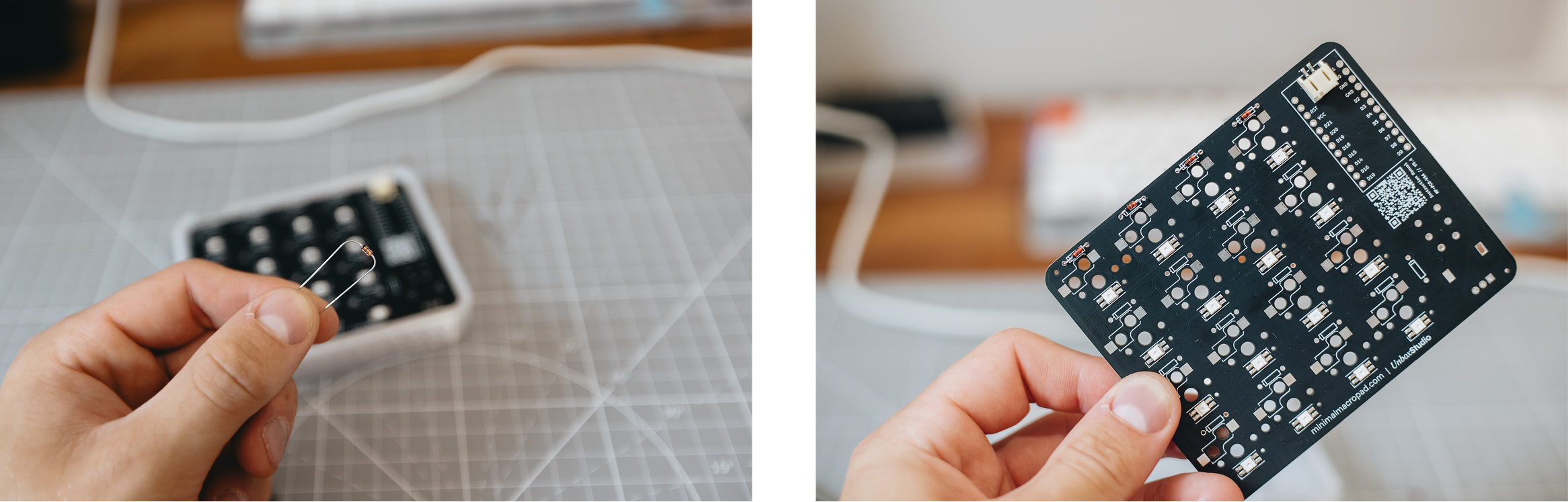
I would suggest soldering the diodes one row at a time. First, look at the image below to make sure the diodes are oriented correctly. Fold each diode’s legs 90 degrees around your finger, insert it into the PCB, and bend the legs outward on the back so it does not fall out. Once you have inserted a full row, solder the diodes in place. Then use snips or cutters to trim the legs as flush with the PCB as possible before moving on to the next row.
There are 17 diodes in total—do not forget the one for the rotary encoder on the left. Insert the diodes from the side where they are shown on the white silkscreen, and line up the black band on each diode with the white line on the silkscreen.

Hot-swap sockets
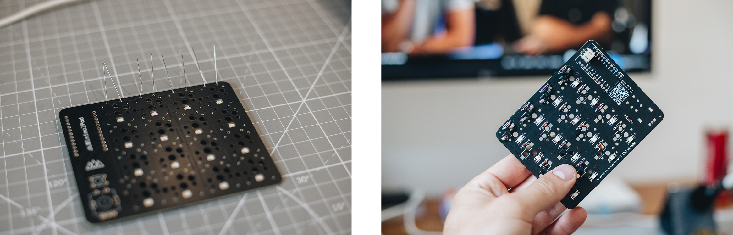
After soldering all the diodes, I would suggest placing the Kailh Choc hot-swap sockets onto the board. They go on the same side and should fit nicely into the two alignment holes. Make sure each socket stays flush with the PCB while you solder it.
To solder a socket, hold the tip of your soldering iron against both the socket’s metal leg and the square pad on the PCB. This heats both surfaces. Then apply a good amount of solder to the pad so the socket is held firmly in place. Work one row at a time so you do not accidentally knock loose sockets out of place.
Microcontroller
After you have soldered all the diodes and hot-swap sockets, it is time to place your chosen microcontroller onto the PCB. Make sure the male header pins are cut to length. They may arrive too long, so use a pair of cutters to carefully trim them. I would suggest inserting the header pins into the PCB first and then placing the microcontroller on top. This helps keep the pins straight.
Start by soldering the four corner pins on the microcontroller side. Flip the board and solder the four corner pins on the PCB side as well. This keeps everything in place while you solder the remaining joints.
Note: The microcontrollers have two pins at the top for an external battery that do not use header pins. Make sure the bottom pins of the microcontroller line up with the bottom pins on the PCB. This means the top two pins of the microcontroller will not have header pins. This only applies to the nRF clone; on the nice!nano v2, these pins are too small for headers anyway.
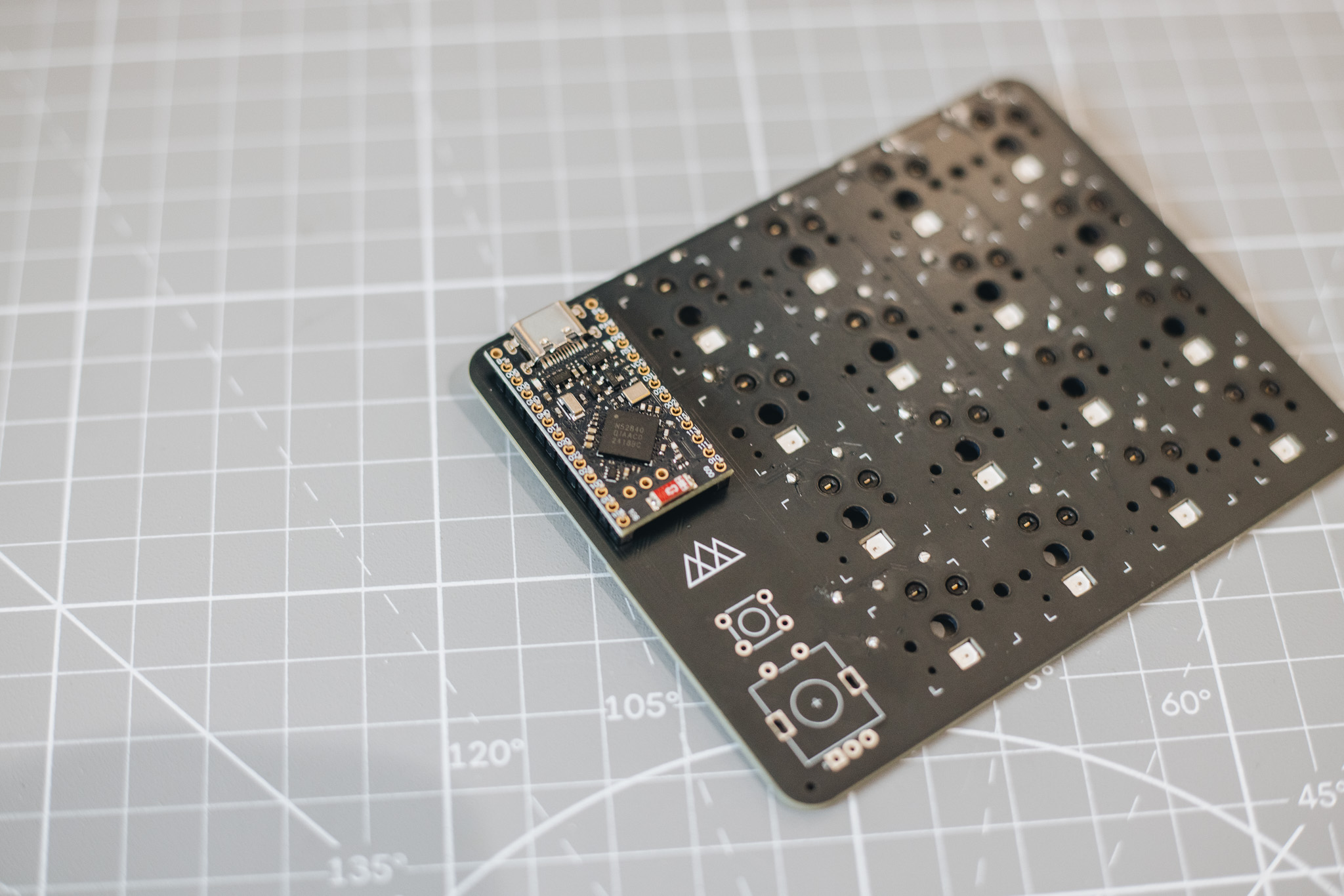
Rotary encoder and push button
With the microcontroller in place, the heavy lifting is done. Now we only need to solder the rotary encoder and the small push button onto the top side of the PCB. Insert the rotary encoder in the correct orientation and solder it from the back of the PCB. Place the push button with its pins on the left and right sides, not at the top and bottom.
Switches and keycaps
Before installing the switches and keycaps, fit the four M2 screws supplied with the kit. If you’re adding a battery, connect and position it inside the case before securing the PCB.
Once the PCB is screwed into the case, install the hot-swap switches from the top. Align the two small pins on each switch with the corresponding holes in the PCB, then press the switch firmly into place. The switch logo may appear upside down, but this is the correct orientation for the LEDs to shine through.
Finally, press the keycaps onto the switches.
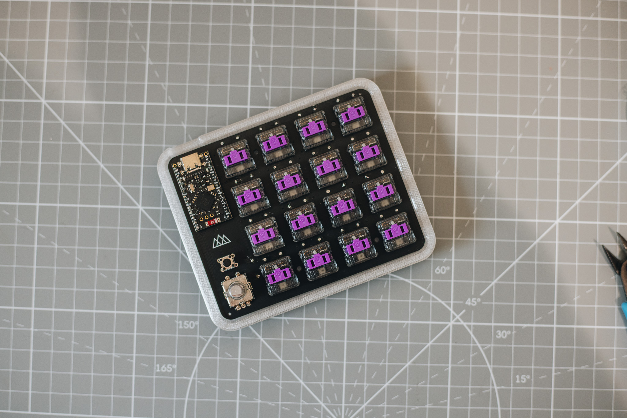
And that is almost it! Place your keycaps onto the switches, then press the knob onto the rotary encoder. Make sure the flat section inside the knob lines up with the flat side of the encoder.
Flashing
You have now successfully built your own MinimalPad! The last step is to flash the firmware and confirm that everything works.
- Connect the MinimalPad using a data-capable USB-C cable. A charge-only cable will provide power, but your computer will not detect the device.
- Quickly press the small PCB push button twice. The microcontroller will enter bootloader mode and appear as a new removable drive.
- Download the latest
.uf2firmware file from the MinimalPad firmware builds on GitHub and drag it onto that drive. The controller should restart automatically when the transfer is finished. - Open MinimalPad Studio in Chrome or Edge, choose USB / Serial, and select your MinimalPad. A green “MinimalPad connected” status means you are ready to test the keys and customize your keymap.
For the complete USB setup and quick troubleshooting, see the MinimalPad USB connection guide.